SFP28 and QSFP28 Transceivers Cabling Solutions
Due to the increasing number of connected devices in use and their need for fast cloud-based data processing, the Ethernet interconnect standard widely used in data centers is evolving to move data more quickly and efficiently, which has driven the development of a 25Gbps version of Ethernet. Before 25G Ethernet was proposed, the next speed upgrade for data centers was expected to be 40G Ethernet (using four lanes of 10G) with a path to 100G defined as using 10 lanes of 10G as shown in the following table. However, the 25G Ethernet standard can provide a path to 100G and achieve higher total bandwidth than 40G. This article will discuss the different connection methods between 25G SFP28 and 100G QSFP28 transceivers.

Note: 100G QSFP28 can be interfaced with 12-fiber MTP connector or duplex LC connector. In this post, the QSFP28 modules we mentioned all have MTP interface.
Direct Connectivity Solution
According to standard, since QSFP28 is 100G interface, SFP28 is 25G interface, four SFP28 transceivers must be needed to connect to one QSFP28 transceiver to achieve 25G to 100G transmission. In this scenario, an 8-fiber MTP-LC harness will be required to direct connect a QSFP28 port to the four corresponding SFP28 ports. This harness cable has four duplex LC connectors and the fibers will be paired in a specific way, assuring the proper polarity is maintained. Keep in mind that this direct connectivity method only recommended for short distance within a give row or in the same rack or cabinet.

Interconnect Solutions
Solution 1: This interconnect solution shown in the image below allows for patching on both ends of the optical network. The patching on the QSFP28 end is accomplished by using Type-A non-pinned MTP to non-pinned MTP jumper, which connects to the trunk cable, while the patching on the SFP28 end is accomplished using MTP modular cassette and duplex LC patch cable.

Solution 2: In this scenario, a Type-B non-pinned MTP to duplex LC breakout cassette will be used to breakout an 8-fiber QSFP28 transceiver into a 2-fiber SFP28 patching field. This solution does reduce the amount of system attenuation by removing a MTP connector pair, however, it would be that the port breakout module has a limited tail length. Besides, this cabling solution only works best when the active equipment being connected is within the same row.

Solution 3: This interconnect solution allows for an easy upgrade path moving from 2-fiber to 8-fiber connectivity. To connect to the SFP28s ports use the 8-fiber harness as shown in the following diagram, and an 12-fiber MTP trunk cable would be used from the adapter panel for the QSFP28 connectivity, thus allowing a mix and match upgrade patch without having to change out the patch panels. The SFP28 transceiver ports need to be located in the same chassis, which creates less flexibility.

All the products introduced in the above solutions including SFP28 transceivers, QSFP28 transceivers, MTP breakout cassette, MTP adapter panel, MTP trunk cable, etc. can be purchased in FS.COM. We provide free and the same day shipping to the US now.
How to Deploy High Density MTP/MPO Cables in 10G/40G/100G Migration?
Just as large enterprise settle into 10G networking, bandwidth intensive applications and big demands are forcing companies to adopt 40G or even 100G network speeds. To address the upgrading from 10G to 40G/100G more efficiently and effectively, high density MTP/MPO cables are a good solution. In this post, I’d like to introduce the deployment of MTP/MPO cables (MTP harness cable, MTP trunk cable and MTP conversion harness) in 10G/40G/100G migration.
10G to 40G Migration: 8-Fiber MTP Harness Cable
8-fiber MTP-LC harness cable is one commonly used solution to directly connect 10G device to 40G device. As the following image shows, the MTP harness cable is in conjunction with a QSFP+ port carrying 40GbE data rates, then breakouts into four LC duplex cables which will be plugged into four 10G SFP+ transceivers.

40G to 40G Connection
Solution 1: 12-Fiber MTP Trunk Cable
For 40G to 40G direct connection, 12-fiber MTP trunk cable is the first choice. In the following scenario, 12-fiber MTP trunk cables are needed to connect the 40G transceivers (four fibers transmit, four fibers receive, leaving four fibers unused), adapting to the QSFP+ ports on the two 40G switches.

Solution 2: 2x3 MTP Conversion Module
In this scenario, 2x3 MTP conversion module is used. For every two 12-fber MTP connectors in the backbone cable, you can create three 8-fiber links. There is an additional cost for the additional MTP connectivity, but that is offset by the cost savings from 100 percent fiber utilization in the structured cabling. The 2x3 conversion module must be used in pairs—one at each end of the link. As the following image shows, the eight live fibers from each of the three QSFP+ transceivers are transmitted through the trunks using the full 24 fibers. The second 2x3 module unpacks these fibers to connect to the 3 QSFP+ transceivers on the other end.

Solution 3: 2x3 MTP Conversion Harness
For those needing a direct connection with 100 percent fiber trunk utilization, 2x3 MTP conversion harness (two 12-fiber MTP connectors on one end going to three 8-fiber MTP connectors on the other end) is an alternative fanout solution available which has the same functionality as 2x3 conversion module. Connectivity of the conversion harness is identical to the 2x3 module, and they are interchangeable, but must be used in pairs—one (cable or module) at each end of the link.

10G to 100G Migration: 20-Fiber MTP Harness Cable
CFP is a very popular implementation when deploying 100G network. To achieve 10G to 100G migration, in this scenario, 20-fiber MTP LC harness cable will be used(ten fibers for transmit and ten fibers for receive, then breakout into ten duplex LC cables). Simply connect this cable to a CFP transceiver and the customer can access the 10 SFP+ individually transceiver pairs.

100G to 100G Connection: MTP Trunk Cable
For directly connecting switches with QSFP+ ports, 12-fiber MTP trunk cable can be used, while for connecting 100GBase-SR10 CFP equipped devices, 24-fiber MTP trunk cable will be deployed.

Conclusion
From the text above, we have introduced several 10G/40G/100G scenarios that use MTP/MPO cables for data transmission. MTP trunk cable is a common solution for device direct connection, MTP harness cable is used for easier upgrading to higher speed network, and MTP conversion harness can achieve 100% fibers utilization, saving costs. All the MTP/MPO cables that we mentioned can be purchased in FS.COM.
Things Should Be Noticed Before Choosing 24-Fiber MPO Cable
In the process of migrating to greater bandwidth 40G and 100G network, MTP cabling system which provides high density and high performance plays an important role. Whether to use 12-fiber or 24-fiber MPO cable has been a hot topic in higher speed networking migration. In my previous blog Choosing 24-Fiber MPO/MTP Cabling for 40/100G Migration, we have indicated that MPO 24 cable is more suitable for 40G and 100G network. Besides, with active equipment planning to use a single 24-fiber MPO interface for 100G and the channel currently requiring 20 fibers, many IT managers are also considering the use of 24-fiber MPO solutions. However, before choosing 24-fiber MPO cable, there are some facts that should be noticed.
The Higher the Fiber Count, the Higher the Loss
Optical loss budget is a big concern among data center managers, and due to limitations in the protocol, standards now require a total connector loss budget of 1.0 dB for 40G and 100G, but a 24-fiber MPO connector typically has a loss of 0.5dB which is much higher than 0.2dB that 12-fiber MPO connector has. This is mainly due to the fact that the more the fiber count, the higher the loss. The higher loss of the 24-fiber MPO limits data center managers to having just two mated pairs in a channel.
Note: Current proper polishing technique can address 24-fiber MPO to meet the low loss requirement as 12 fiber MPO connector. For example, 24-fiber MTP trunk cable in FS.COM only has 0.35dB insertion loss.
The Higher the Fiber Count, the More Difficult to Control End-Face Geometry
In a quality fiber connector, the fibers protrude slightly beyond the ferrule. When two fibers are mated using the right pressure, the fibers will deform slightly to fill in any gaps and provide a solid mating. Any variance in the pressure can impact the insertion loss and return loss on a fiber-to-fiber basis. To achieve consistence pressure, it is important to have a very flat ferrule after polishing with all the fibers protruding equally. With higher count arrays, like 24-fiber MPOs, there are more fibers to control, which can significantly increase the odds for height variance. For example, in the following 72-fiber array, if we look at this graphic of the middle two rows of fibers, we can see the variance in the height profile. The height variance becomes even more pronounced across more rows of fibers. Besides, it is more difficult to achieve a flat ferrule polishing on a large array area.

Although the polishing technique has been significantly improved, there still exists limitation to achieve a flat end-face and equal pressure over the array.
Standards and Testing Remain an Issue to 24-fiber MPO Cabling
100GBase-SR4 standard has be a reality and that most of users is running 100G over 8 fibers, rather than 20, which will render the 24-fiber MPO a dated interface for 100G Ethernet. In addition, the MPO cabling testing is far more complicated than duplex cabling testing. You have to gain very professional training, tools understanding that you can efficiently conduct multifiber testing. In other words, if there is any issue with the multifiber cabling, it’s not easy to troubleshoot it.
It's Still Your Choice
With the significant demand for higher speed 40GbE and 100GbE, MPO cabling has become more popular than ever. We have indicated that 24-fiber MPO cable reveals more advantages than 12-fiber MPO cable, however, before choosing it, there are more factors we have talked above that should be taken into consideration.
How to Deploy 10G, 40G, 100G in the Same Network
In 2010, 10G SFP+ became the primary equipment interface in data center applications. However, jump to 2017, as demand for greater bandwidth shows no signs of slowing, 40G and 100G transceiver shipments saw a whopping increase. While shipments of 40G and 100G modules are on the rise, the large majority of data center networks don’t undergo a whole replacement of 10G device with 40G or 100G device. Instead, many typically deploy necessary equipment to achieve the coexistence of 10G, 40G, and 100G in the same network. Read this post, and you will get detailed solution.
QSFP+ 40G to 10G
In the following scenario, an upgraded 40G switch is networked to existing 10G servers with a 1x24-fiber to 3x8-fiber MTP conversion cable. At the switch, a cassette combines three 40G ports (QSFP 8-fiber) on the 24-fiber trunk. In the server cabinet, each 40G port is segregated into 10G LC connections to support server connectivity.
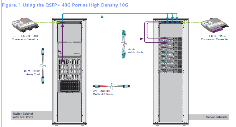
Note: in this architecture, if you have existing 12-fiber MTP trunks, you can use a cassette with two 12-fiber MTP inputs that breakout into 3x8-fiber MTP strands, instead of deploying a new 24-fiber MTP trunk cable. However, if you have to move to denser and more complicated applications, the 24-fiber MTP solution makes for easier migration.
CFP2 100G Port (10x10)
Like the previous example, the following figure 2 also shows a similar scenario in existing 10G servers, but it uses 100Gbase-SR10 ports on the switch, which requires a 24-fiber connector to drive the 10x10 transceiver port. Instead of breaking into 8-fiber connections, it uses 24-fiber MTP patch cord from the switch to the patch panel in the top of the rack. A 24-fiber MTP trunk connects the switch and server cabinet. The MTP cassette at the top of the server cabinet converts the 100G port into ten individual 10G port with LC connectors.
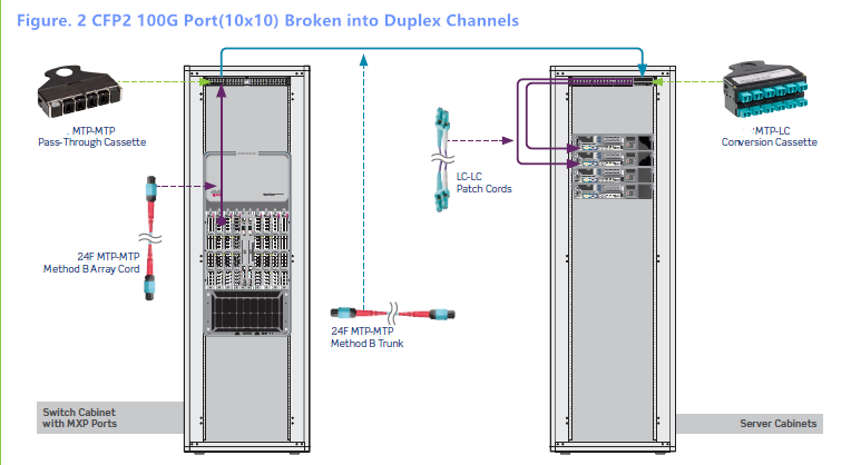
Note: As in the figure 1, in this scenario, if you already have two 12-fiber MTP trunks, you can use 12-fiber MTP adapter panel, then a 2x12-fiber to 1x24-fiber MTP harness cable could be used at the switch to build the same channel.
New Installation for 40G/100G Deployment
Figure 3 shows an example of a completely new installation, using 40G/100G right out of the box without any 10G switches in the channel. This method has 40G or 100G port on the core switches, and 40G uplinks at the ToR switches. The patch panels at the top of each rack use MTP bulkhead, with all 8-fiber cords from one QSFP port to the next.
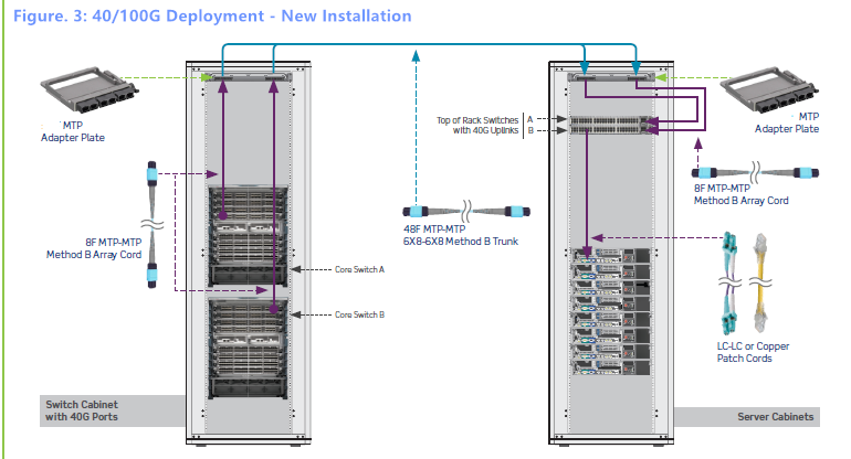
In this architecture, we can either use 24-fiber trunks that break into 40G ports, or create trunks with 8-fiber strands on every leg, with 8 fibers per 40G or 100G port, as shown in the diagram above. However, we have to pay attention that with 8-fiber legs, the density will become a challenge. In addition, 12-fiber MTP trunks are avoided in this scenario, since integrating existing 12-fiber trunks with 8-fiber connectivity on the patch cord creates fibers unused.
Deploying 10G, 40G, 100G in the same network can effectively avoid costly upgrades that require ripping out cabling and starting over with a new network architecture. This post have provided three solutions. All the devices in these three scenarios can be purchased in FS.COM. If you are interested, kindly visit FS.COM.
Decoding Four types of 100G QSFP28 Transceiver
With the development of IP-based multimedia service, especially video service, network traffic has been continuously rising. As a result, 40G and 100G have emerged as the key technologies capable of supporting the growth in network bandwidth. After a lengthy period of hype, 40G technologies have finally widely been deployed. And now it is 100G’s turn. While 100G networking may seem excessive to many right now, there are many industries where that 100G speeds are quickly becoming necessary. This post will introduce four QSFP28 transceiver types that are commonly used in 100G data center.
QSFP-100G-SR4
QSFP-100G-SR4 or 100GBase-SR4 QSFP28 optical transceiver is a full duplex, photonic-integrated 100G module, which uses 4 fibers for transmit and 4 for receive, with each lane supporting 25Gbp, providing an aggregated data rate of 100Ggps as shown below on up to 70m of OM3 MMF and to 100m of OM4 MMF. Like 40GBase-SR4, 100Gbase-SR4 uses a MPO 12 cable with 4 strand for transmit and 4 for receive, allowing for existing 40GBase-SR4 fiber assemblies to be reused when higher performance is needed. This interface standard has been introduced alongside the 100G QSFP28 offerings now, arriving on the market in order to make any 40GbE to 100GbE upgrade as seamless as possible.

QSFP-100G-LR4
QSFP-100G-LR or 100GBase-LR4 QSFP28 is another 100G standard, which focuses on longer data transmission up to 10km over single-mode fiber. Like 40GBase-LR4, the 100GBase-LR4 is also a multilane optic. However, each lane’s data rate is increased to 25Gbps. It has duplex LC interface and uses WDM technologies to achieve 100G dual-way transmission over four different wavelengths around 1310nm that can be seen in the image below.

QSFP-100G-PSM4
Targeted to service the need on a parallel single-mode infrastructure, 100G PSM4 module is a low cost solution to long reach data center interconnect. It uses four parallel fibers (lanes) operating in each direction, with each lane carrying a 25G optical transmission as shown below. Interfaced with MPO connector, it can support distance up to 500 meters over single-mode fiber, which covers a wide rage of applications in data center.

QSFP-100G-CWDM4
Backed by the CWDM4 MSA Group, 100G CWDM4 is a 100G interface that address data communication links up to 2km in the data center. The CWDM4 architecture employs 4 lanes of 25Gbps using CWDM technology to transport 100G optical traffic across duplex LC single-mode fiber. Compared to 100GBase-LR4, CWDM4 is an alternative for long transmission distance in data center. The working principle can be seen in the following image.

Summary
100G Ethernet is no longer a fantasy, and it is on the way. QSFP28 is a key to the 100G deployment. In the part above, we have introduced four types QSFP28 modules widely used in 100G network. All of these modules that have been tested and are 100% compatible can be purchased in FS.COM. If you have any related requirement, kindly visit FS.COM.
Why Choose Base-8 MTP Link for Future-Proofing Your Network?
When deploying a new fiber system, data center managers will always consider whether the system can be easily upgraded to higher data rate network or not in the future, since network reconfiguration will cost much time and money. So choosing a right fiber optic link is the very step to ensure an efficient, future-proof data center. Here, we highly recommend Base-8 MTP link for your home network or data center. Why? Please continue reading the following text.
More Flexible
As we all know, 40G and 100G applications prefer to use parallel SR4 optics (four fiber for transmitting and four fiber for receiving) to transmit data rates. Base-8 connectivity makes use of fiber links in increment of 8 versus 12 or 24, which can allow customers to patch directly to SR4 transceivers without having to convert connectors with different counts or waste fibers in the backbone. Therefore, if customers who still run 10G data rates deploy Base-8 MTP link at the very beginning could migrate to 40G, 100G or beyond without changing the current fiber link, which is more flexible and easy.
High Investment but High Return
Actually, compared to Base-12 and Base-24 backbones, Base-8 link requires higher investment, since more MTP connectors will be installed from the start. However, as we have mentioned above, Base-8 is the most suitable solution for SR4 applications which means that if managers plan to upgrade to higher speed 40/100G network, no additional conversion cable or conversion modules will be needed, bringing a higher return in the future.
100% Fiber Utilization
In most 40/100G cases, Base-12 backbones are more recommended to use between core switched and the equipment distribution area in the data center, but actually, there is no standardized transceiver using all 12 fibers in a Base-12 MTP connector. Besides, with more and more data center managers prefer to use SR4 interface in 40G and 100G applications, using Base-8 link can achieve 100% fiber utilization. So do you still insist on deploying Base-12 today and risk wasting 33% of backbone fibers as shown in the image below tomorrow, or going straight with Base-8 knowing that it will be the best investment in the future?

Summary
When deploying a new fiber link, we should consider in the long term instead of in the short term. All the proof that we have talked above have indicates that Base-8 MTP link will be the best solution for future-proofing your network. With Base-8 MTP link today, we can easily upgrade to 40G or higher speed network tomorrow.
Patch Panel Plays a Role in High Density Cable Management
In a structured data center cabling, patch panel is a functional unit which can increase efficiency and the usefulness of the such a cabling. Without it, the transmission of data is rendered ineffectively, it consolidates all the horizontal cabling in any piece of infrastructure, allowing IT managers to terminate long and troublesome cables so that a signal is connected directly through a patch code to its destination. This post aims to introduce patch panel in the following text.
What More Benefits We Can Get from Patch Panel
Patch panel is a device which enables cable connections, usually involving a short cable plugged in the front and a long cable into the back of the patch panel. The primary advantage of using patch panel is improved organization and easier management of your network. It also serves as the nerve center for the cabling network. Simply put, the patch panel is where all the horizontal cabling in the infrastructure is consolidated. Besides, patch panel plays a central role in the administration of the telecommunications network by enabling the process of moves, adds and changes (MACs) in complex spaces. For example, if two workers must transfer desk locations, a simple switch of patch cords into various ports on a patch panel can ease the move. Without this capability, much time and energy would be spent termination cable that would have to be hard-wired. Here shows Cat5e patch panel.

Patch panel is so critical to a system that if anything goes wrong with them, the entire system may fail, so it makes sense to choose patch panels carefully.
Copper VS. Fiber Patch Panel
Generally, there are copper and fiber patch panel available on the market. Some professionals are adamant that there is no real differences in the performance and construction, while others see a drastic differential between the copper and fiber products.
Cost: Cost is always the key consideration that most IT managers will concern. Commonly, the cost of fiber patch panel which having improved over the past year is far more than the copper equivalent. Such explains that the cost of actual installation is compatible but estimate a 30% to 40% per premium for fiber patch panel. Take FS.COM as an example, a 24 port Cat5e patch panel is only $41, but a MTP patch panel for 40G is about $850.

Ports Requirement: If we compare these two patch panels from the ports that they need, there is a night and day difference between copper and fiber patch panel. With copper panel, each pair of wires has one port, while fiber patch panel requires two port—one for the transmit end and one for the receiving end, because each tube of glass can only transmit in one direction.
Installation: Most professionals believe that fiber patch panel is a lot simpler to install than copper panel. A copper patch panel typically has up to four or eight modules, each with eight ports, which bring a total of 32 and 64 ports respectively. However, a traditional fiber patch panel typically features 72 or 96 ports, and some fiber panel may have up to 1,536 ports. (Note: The number of ports on a panel is not subject to physical limit other than the room to place them.) A high port count is required since two ports must accommodate each fiber cable.
Summary
Patch panel is highly functional systems, and will not at any point stand in the way of modifying your office or business design. FS.COM provides both copper fiber patch panel (Cat5e and Cat6 patch panel) and high density fiber patch panel (MTP patch panel) for different requirements. For any detailed information, please visit FS.COM.